Over the past couple of weeks, I’ve spent entirely longer than I probably should have falling down the rabbit hole that is the game Turing Complete.
In a nutshell, you start with basically nothing, build up simple logic gates, create memory cells and 1-bit addition, build that into 8-bit math and logic, read instructions RAM, implement loops, and function calls (in hardware!), and eventually use your very own custom built CPU to solve a few programming challenges.
If that sounds at all interesting to you, I highly recommend it. It’s a well laid out program and I had a lot of fun going back to my computer engineering days in undergrad!
In any case, I wanted to share my final CPU (as a sort of ’last look’ before I can finally move on to other things). I have the language that I ended up designing, which is roughly based on the one they had you designing, but I redid decent bits of it to add some more features and clean it up (in my opinion).
So below, we have:
First, we’ll talk about the language that I designed the CPU around, then pictures of the virtual CPU hardware, and finally a few assembly programs that I actually ran on this (virtual) hardware.
I’d absolutely love to try to build this or program it onto an FPGA or something like that, but I think that’s a problem for another time. 😄
Requirements
Okay, first up, what requirements and/or design specifications did we have for our virtual machine?
- 8-bit instructions, registers, and memory - I did consider bumping this up, the game has components scaled up to 64-bits for you, but I didn’t end up needing it, so didn’t implement it
- Basic arithmetic and logic operators
- The ability to decode instructions from a program RAM
- These instructions should allow variable width operations; this is a difference from the architecture the game leads you to; all of those instructions are exactly 4 bytes
- Registers for short term storage
- A stack based memory system for longer term storage (you don’t really need this, you can implement it in RAM)
- 256 bytes of RAM accessed by address
- 256 bytes of persistent RAM/ROM (I only used this for an alternate solution to one problem; it’s the last thing I implemented)
- All instructions can be conditional (similar to what SHENZHEN I/O does and another departure to how the suggested architecture runs)
- Jumps (for loops) and function calls (with a proper stack for recursion)
Final Language Specification
So, how do I set that up?
Flags
Okay, first things first, I want all instructions to be stored in a single byte with 0-2 arguments after that. As mentioned, all instructions can be conditional (similar to what SHENZHEN I/O does) and I directly encode the arity into the function name. So for the first byte, we end up with something like this:
cnpp oooo

c - conditional bit; if the 'conditional' flag is not set, skip this instruction
n - unconditional bit; does the opposite of c (if both c and n are set, weird things happen)
pp - number of args / how much PC should be advanced 01/10/11 for 1, 2, 3; 00 signifies a jump
oooo - opcodes
If the highest bit (c) is set, only run this instruction if the conditional flag is set (I’ll come back to this). If n is set, only run if conditional is not set. Set both to 0 for an unconditional operation and both being 1 is an error and will halt the CPU.
When I’m encoding this in assembly programs, it looks like this:
add r0 r1 r2    # not conditional
c|add r2 5 r3   # conditional
n|add r2 7 r3   # negative conditional
Arity / pp bits
After that, two bits (pp) that specify the arity of the function. This is constant for any ALU based operations and strange things™ will happen if this is not correct. This does mean there are a number of nonsense parameters that can probably be abused in various ways (like pp = 01 for add would run the add and then set the PC to what should be the b parameter).
Let’s just call that undefined behavior. 😄
Okay, now the actual operations.
ALU/Logic Opcodes
For anything with pp != 00, we basically have our ALU first:
0000 add {in_a} {in_b} {out}
0001 sub {in_a} {in_b} {out}
0010 mul {in_a} {in_b} {out}
0011 div {in_a} {in_b} {out}

0100 not {in} {out}
0101 and {in_a} {in_b} {out}
0110 or {in_a} {in_b} {out}
0111 xor {in_a} {in_b} {out}
It’s … certainly a choice to have a hardware div, but they gave it to me (once I implemented it in assembly on my CPU first), but we’ll go with it.
RAM/ROM/Stack Operations
Next up (still with pp != 00), we have memory based instructions:
1000 store {in_a} {addr} - store the value in in_a to the address in_b
1001 load {addr} {out} - load the value from the address in_a to out
1010 push {in_a} - push the value in in_a to the stack
1011 pop {out} - pop the value from the stack to out
These will store/load from RAM (by default) or persistent RAM/ROM (if mode_rom has been set, see below) or alternatively push/pop from stack memory.
I really could have just dropped the stack, I didn’t end up really using it much. It can actually be used directly as an offset in A/B parameters, but I didn’t actually do this. 🤷
Conditionals
Next up, conditional functions. These don’t do anything (much) themselves, but instead will set the conditional flag until the next time that a conditional function is called:
1100 ceq {in_a} {in_b}
1101 cltu {in_a} {in_b} - compare less than unsigned
1110 clt {in_a} {in_b} - compare less than signed
1111 cle {in_a} {in_b}
Jumps/Mode switching (pp == 0)
And finally, we get to the case where pp == 0, which is jumps, function call, and also the only place I could fit mode switching (when I added that at the last minute):
0000 jmp {in_a} - absolute jump (8bit)
0001 jmp16 {in_a} {in_b} - absolute jump (16bit) (not implemented)
0010 rjmp {in_a} - relative jump
0011 rjmp16 {in_a} {in_b} - relative jump (16bit) (not implemented)

0100 call {in_a} - call subroutine (8bit)
0101 call16 {in_a} {in_b} - call subroutine (16bit) (not implemented)
0110
0111 ret - return from subroutine

1000 halt

1010 set store/load mode -> ram
1011 set store/load mode -> rom
Originally, I was set up so that I could use a pair of values in order to jump to 16-bit values so I could have programs longer than 256 bytes. But… I didn’t need it, so the **16 operations never ended up used.
In addition, call does not preserve registers. You have to do it yourself, which is something I do in the Tower of Alloy problem and (for the one and only time) use the stack for that. I did plan to automatically store the first three registers (r0 to r2; since we can read/write 4 bytes at a time) but never implemented it. So it goes.
Parameters
Okay, that’s enough to specify the instructions, what about those actual parameters that the arity / pp specify?
Well, for input, we can have immediate values (positive if the first two bits are 00, negative if 01). Then we can also read the nth value down the stack as a parameter (10 prefix), which I never used. And finally, if the prefix is 11, then we have the 6 built in registers + stdin (11-- -111).
{in_a / in_b}
  00vv vvvv - positive immediate
  01vv vvvv - negative immediate
  10-- nnnn - the nth value on the stack
  11-- -rrr - registers r0-r5; 110 reads SC, 111 reads IN
And likewise, for output… we only have the registers (11-- -111 is stdout).
{out}
    1--- -rrr - registers r0-r5; 110 does nothing, 111 writes to OUT
And… that’s it (isn’t it enough? 😄), let’s get onto the hardware!
Final Hardware
Okay, we have a language. Next step is to build something that can actually run that!
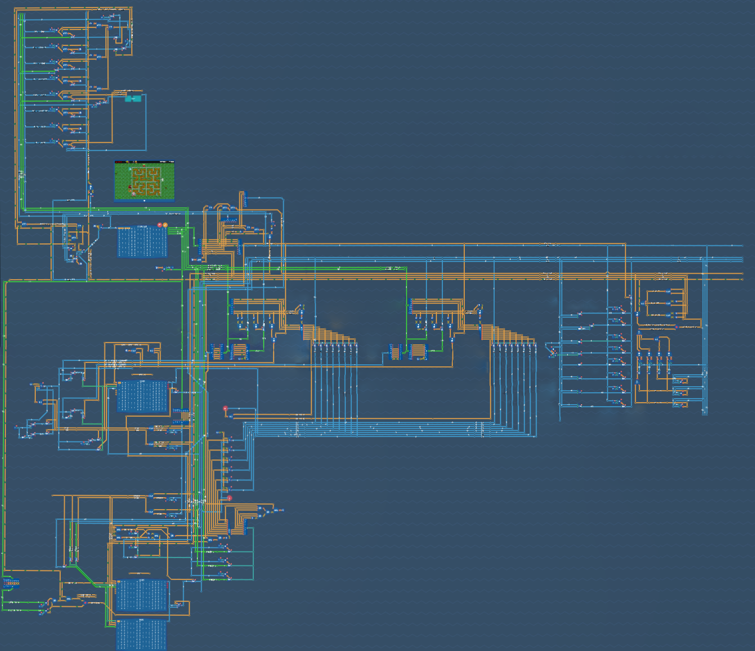
For any of these images, you can right click, open image in a new tab to see the full size image. The first two overview images are already zoomed pretty far out though, so you really can’t see details or comments.
If you want a bit more detailed map, here are the various regions of the CPU:
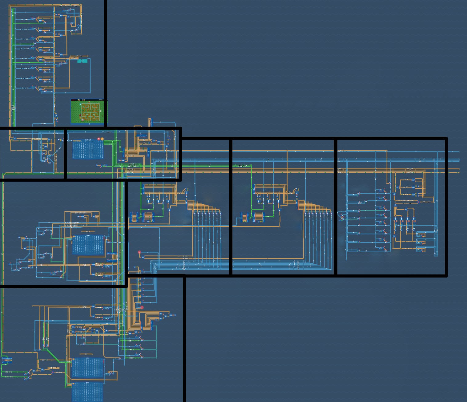
From top left down rows, we have:
- In the top left, the jump decoder
- Below that, we have a circuit to update the PC and decode the program
- In the 3rd row, far left, we have stack memory
- The next two in that row are decoders for A input and B input
- The final block in the third row is the ALU
- The bottom left is the system RAM and ROM
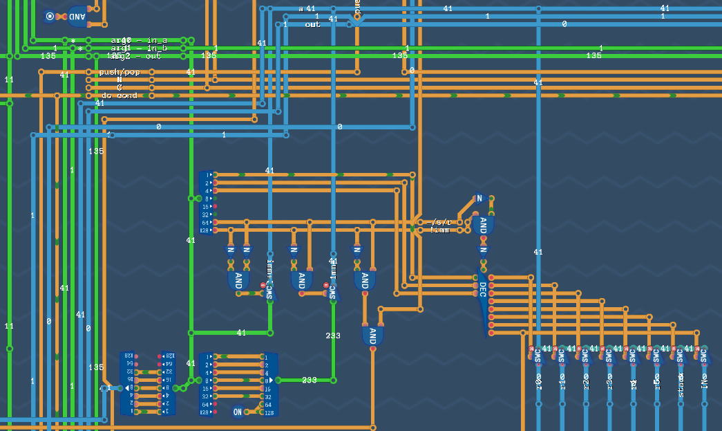
The decoder
Okay, first, we have the program encoder itself.

In here, we always read 4 bytes, even if we’re not going to use them. To the left of the PROGRAM, we have the PC with a bunch of logic:
- If we have
pp != 0, advance byppbytes - If we have
pp == 0, use the jumpppcalculator to set the next value
To the right, we decode the initial instructions creating several interesting values. Such as p0 and p1, a flag if we’re doing a push/pop, if we’re running an ALU operation (do_op), and the N and C flags (we’ll come back to those in the conditional hardware).
Register input decoder
Next up, we have two copies of our input decoders. Primarily, these will read from the registers (which are input in the bottom right of this image), stack address, or INPUT. If we have an immediate value, those are parsed (and expanded for the negative case) in the bottom left of this image. THis is then set up to the very top blue line (A) for use by the ALU.
This is duplicated for the B input immediately beside here.
ALU
Next up, the ALU itself (and conditional logic).
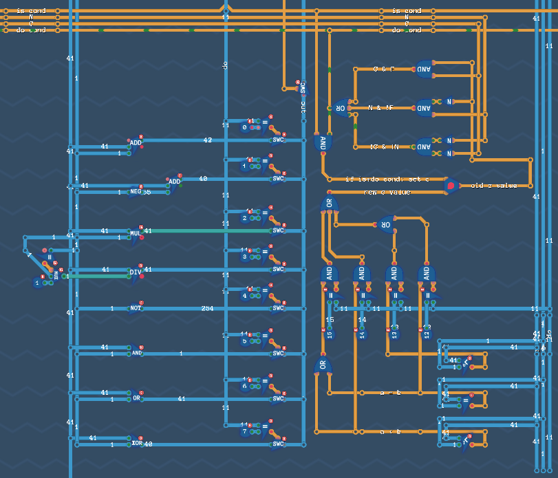
Here, we will take whatever was put on A and B above and in parallel calculate all the possible ALU operations. This is then selected by what the opcode actually was an sent back out to the third blue line on the main bus: out.
In addition, on the right side here, we have the conditional flag and code.
Basically, if we are running one of the four conditional operations, we will select the combination of < (signed and not) or = and then set that into the conditional flag. One wrinkle here:
ceq r0 0
c|ceq r1 0
...
What does that do? Checks if r0 == 0 && r1 == 0. Because the second operation is itself conditional, we only update the register if it was already true. If it was false, it doesn’t run and we end up with conditional flag = N for the next instructions(s).
In a nutshell, that’s why we have the if is+do cond; set c comment. 😄
Jump engine
Okay, jumping (heh) from there, we have the code that handles jump instructions.
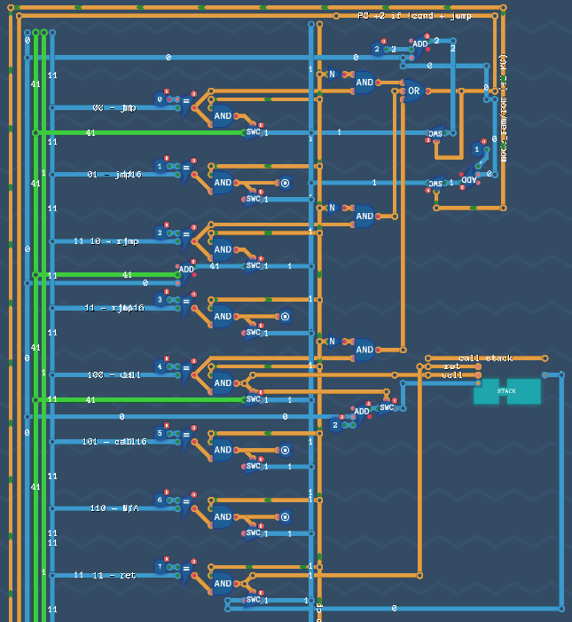
Here we have a pile of possible instructions in parallel (even if half of them have ‘halt’ nodes, for the 16 bit versions). If a specific instruction is decoded, then we will update the PC using that one. One caveat though: these can be conditional! If C or N is set. So if it is, use the new value for PC. If not, always advance by 2 for everything but ret, which advances by 1. Yay hardcoding!
This also does handle the special case of mode instructions (since they don’t have parameters, but should advance 1).
Finally, we have a STACK there. That’s used for call (the current PC is pushed to the stack; +2 to not run the call again on ret) and ret (the most recent call address off the stack). Whee!
Stack memory
Okay, next up, just below the program decoder, we have the stack:
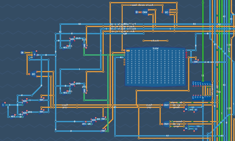
Mostly, we implement push and pop here.
But–you might ask–this isn’t a STACK, this is a RAM?!
Why? Because we do also have to set the in_a_from_stack (and the same for b) if we have a parameter that’s reading from teh stack. This… was not worth it. So we have to be able to access further down than a single value. So it goes.
RAM and ROM
Finally, we have RAM (implemented early) but also ROM (which is really more of ‘persistent’ RAM / a hard drive):
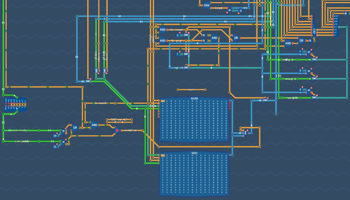
These basically work the same way and take the same input/output/address values as each other. We do have to make sure that we have the correct instruction though, so we don’t accidentally write to ROM when we meant RAM and vice versa.
This flag just the left of the RAM banks specifies which one we will store to/load from.
One gotcha here: the ROM/HDD isn’t directly addressed. Instead, the address line is how much to seek. So if you run a series of commands like this:
store 42 1
store 57 2
store 99 3
If we’re in RAM mode, we’ll have:
0 42 57 99 0 0 0 ...
But in ROM mode, we’d have:
42 57 0 99 0 0 [0] ...
Because we store 42 and advance 1, then store 57 and advance 2, and finally store 99 and advance 3 (so the next store will go to that [0]).
Yay little gotchas!
Solutions (Assembly Language)
Okay, enough about the hardware, let’s talk a bit about the assembly language solutions I actually implemented using this hardware to solve various problems.
AI Showdown
Okay, for the first problem, we have an ‘interview’ problem I’ve seen before. You’re playing a card game against a(nother) robot. You have a stack of cards and take turns drawing 1, 2, or 3 cards. Whoever draws the last card loses.
This actually has a perfect solution, which is based on the current remainder at each step. So that’s exactly how I solved it:
- Loop
- Calculate the current remainder/mod 4
- For each specific case, send a specific output value and then jump back to the loop
That’s it!
label loop

  add in 0 r0
  div r0 4 r1
  mul r1 4 r2
  sub r0 r2 r2 # r2 is remainder

  # mod 0, take 3
  ceq r2 0
  c|add 3 0 out
  c|jump loop

  # mod 1, we lost!
  ceq r2 1
  c|add 1 0 out
  c|jump loop

  # mod 2, take 1
  ceq r2 2
  c|add 1 0 out
  c|jump loop

  # mod 3, take 2
  ceq r2 3
  c|add 2 0 out
  c|jump loop

halt
That halt at the end should never be reached, but is a remainder of our older testing code.
Planet names
Second problem, string processing!
You’re given a string (which is a list of planet names, all lower case letters, in ASCII). Capitalize the first letter word (the first letter after a space) in a string.
const last_space r0
const char r1
const space 32

# r0 is 'last character was space'
add 1 0 last_space

label loop
  add in 0 char

  # if last was space
  ceq last_space 1
  c|sub char space char
  c|add 0 0 last_space

  # out the (maybe mod) character
  add char 0 out

  # if new character is a space
  ceq char space
  c|add 1 0 r0
  jump loop
Here we see that we can name registers using the game’s built in const syntax. It does make debugging easier. Other than that, you have the ceq char space to set the last_space flag and one interesting bit of ASCII knowledge: If you add/subtract a space (which is ASCII 32), you swap between upper and lower case letters!
And that’s it!
Robot Racing
Run a maze (which is actually a Hilbert curve) using a robot that can only move in 4 directions (up, down, left, right).
const right 0
const down  1
const left  2
const up    3

call urdr call move
call rulu call move
call rull call move
call dluu call move
call rulu call move
call urdr call move
call urdd call move
call ldrr call move
call rulu call move
call urdr call move
call urdd call move
call ldrd call move
call dlul call move
call ldrd call move
call ldrr call move
call rurd call move

halt

label urdr
store up    0
store right 1
store down  2
store right 3
ret

label rulu
store right 0
store up    1
store left  2
store up    3
ret

# ...

label move
load 0 out
load 1 out
load 2 out
load 3 out
ret
So… I totally just hard coded this. There is some repetition in which functions are called, but it’s still kind of long and annoying. We’ll come back to this.
Tower of Alloy
Solve the Tower of Hanoi problem using my virtual CPU.
const toggle 5

# read n, src, dst, and spare from input
label loop
  add in 0 r0
  add in 0 r1
  add in 0 r2
  add in 0 r3
  call hanoi
halt

# expects r0=n, r1=src, r2=dst, r3=spare
label hanoi
  # if n==0
  ceq r0 0
  c|call move
  c|ret

  # else

  # h(n-1, src, spare, dst)
  push r0
  push r1
  push r2
  push r3

  sub r0 1 r0
  add r2 0 r4 # spare -> temp
  add r3 0 r2 # dst -> spare
  add r4 0 r3 # temp -> dst
  call hanoi

  pop r3
  pop r2
  pop r1
  pop r0

  # move src -> dst
  call move

  # h(n-1, spare, dst, src)
  # don't need to preserve this time
  sub r0 1 r0
  add r1 0 r4 # src -> temp
  add r3 0 r1 # spare -> src
  add r4 0 r3 # temp -> spare/r3
  call hanoi
ret

# move a disk from r1(src) to r2(dst)
# expects magnet to be off
label move
  add r1 0 out
  add toggle 0 out
  add r2 0 out
  add toggle 0 out
ret
So here we come into proving that our CPU handles recursion! We were given (as a hint) the code for solving the Tower of Hanoi. ALl we have to do is implement it. And because I don’t automatically save any registers, this is the one time I use push and pop to store the current values before making a recursive call and restoring them after.
And that’s it! A (relatively) complicated algorithm built on my very own hardware. A long way from NAND gates.
Delicious Order
This is a sorting problem. We’re given a series of 15 values and have to output them in sorted order.
I just went for a brain dead bubble sort. I expect that (because I have div), I could actually implement merge sort, although I wonder if we’d run into the 256 byte program size limit. That would certainly be interesting to try. Maybe another day.
# read 15
# sort
# output

const r_i r0
const r_j0 r1
const r_j1 r2

const r_j0_v r3
const r_j1_v r4
const r_temp r5

add 0 0 r_i
label read_loop
  store in r_i
  clt r_i 16
  c|add r_i 1 r_i
  c|jump read_loop

add 0 0 r_i
label loop_i # i is r0
  add 0 0 r_j0
  label loop_j # j is r1
    add r_j0 1 r_j1

    # compare j and j+1
    load r_j0 r_j0_v
    load r_j1 r_j1_v

    # are they out of order
    cltu r_j1_v r_j0_v
    c|store r_j0_v r_j1
	c|store r_j1_v r_j0

    # have we finished j loop
	add r_j0 1 r_j0
    clt r_j0 14
    c|jump loop_j

  clt r_i 15
  c|add r_i 1 r_i
  c|jump loop_i

# now we have to output them
add 0 0 r_i
label write_loop
  load r_i out
  add r_i 1 r_i
  clt r_i 16
  c|jump write_loop

halt
I actually did this one twice, since at first (until I started naming registers) I just couldn’t get it right. This one instead loops 15 times. On each loop, it finds the smallest value (and it’s index), writes out that value, and then sets that index to 255 (a sentinel value).
One gotcha (right at the top there): because of how we implement immediates… we can’t have a constant for 255. Oops. But hey, !0 = 255 and we can name it c_255. But we’re constantly using one of our six registers just for this…
# I ... can't make a 255 constant
not 0 r5

const r_read r0
const c_255 r5

label read_loop
  store in r_read
  ceq r_read 15
  n|add r_read 1 r_read
  n|jump read_loop

const r_i r0

add 0 0 r_i
label write_loop
  push r_i
  call output_smallest
  pop r_i
  ceq r_i 16
  c|halt
  add r_i 1 r_i
  jump write_loop

const r_index r0
const r_min_index r1
const r_min_value r2
const r_value r3

label output_smallest
  add 0 0 r_index
  add 0 0 r_min_index
  add c_255 0 r_min_value

  label output_loop
    load r_index r_value

    # skip already written
    ceq r_value c_255
    c|jump skip_done

    # first non-0 value | < current
    ceq r_min_value c_255
    n|cltu r_value r_min_value
    c|add r_index 0 r_min_index
    c|add r_value 0 r_min_value

    label skip_done
    add r_index 1 r_index
    ceq r_index 15
    c|add r_min_value 0 out
    c|store c_255 r1
    c|ret

    jump output_loop
Water World
Solve a relatively common ‘interview’ problem, where you have a 2D heightmap and you have to calculate the amount of water that could be held by it.
This is arguably the ‘hardest’ problem, not because it’s algorithmically terrible difficult (any open space that has a wall anywhere to both the left and right can store water), but because it’s interesting™ to implement.
I did end up implementing that algorithm, using a bitmask to store: if it’s a wall, if there’s a wall to the left, and if there’s a wall to the right. Then, only the ones that are 0, 1, and 1 respectively are counted!
const width 16

const x r0
const y r1
const index r2
const wall r3
const sum r3
const bits r4

# loop 1: walls
add 0 0 x
label loop_x
  add in 0 wall
  add 0 0 y
  label loop_y
    mul y width index
    add x index index

    clt y wall
    c|load index bits
    c|or bits 0b0001 bits
    c|store bits index

    add y 1 y
    clt y width
    c|jump loop_y

  add x 1 x
  add 1 0 y
  clt x width
  c|jump loop_x

# loop 2: look left
add 0 0 x
label loop_x2
  add 0 0 y
  label loop_y2
    mul y width index
    add x index index

    ceq x 0
    c|jump skip_left
    sub index 1 index
    load index bits
    add index 1 index
    and bits 0b0011 bits
    ceq bits 0
    n|load index bits
    n|or bits 0b0010 bits
    n|store bits index
    label skip_left

    add y 1 y
    clt y width
    c|jump loop_y2

  add x 1 x
  add 1 0 y
  clt x width
  c|jump loop_x2

# loop 3: look right
sub width 2 x
label loop_x3
  add 0 0 y
  label loop_y3
    mul y width index
    add x index index

	add index 1 index
    load index bits
    sub index 1 index
    and bits 0b0101 bits
    ceq bits 0
    n|load index bits
    n|or bits 0b0100 bits
    n|store bits index

    add y 1 y
    clt y width
    c|jump loop_y3

  sub x 1 x
  add 1 0 y
  ceq x 0
  n|jump loop_x3

# loop 4: count
add 0 0 sum
add 0 0 x
label loop_x4
  add 0 0 y
  label loop_y4
    mul y width index
    add x index index

    load index bits
	ceq bits 0b0110
	c|add sum 1 sum

    add y 1 y
    clt y width
    c|jump loop_y4

  add x 1 x
  add 1 0 y
  clt x width
  c|jump loop_x4

add sum 0 out

halt
Robot Racing (now with more cheating)
Okay, I lied. One more. Back to the Hilbert curve problem. One of the achievements for this game is to solve the entire problem in less than 64 bytes…
Given everything you’ve seen, you might be able to guess how I ‘solved’ this one. 😄
mode_rom

label loop
  load 1 out
  jump loop
That’s so dumb. But also so awesome. Basically, I have persistent memory now, so before running this problem, I run a different one to just store all the moves in order in persistent memory:
const right 0
const down  1
const left  2
const up    3

mode_rom

store up 1
store right 1
store down 1
store right 1
...
store right 1
store up 1
store right 1
store down 1
And it’s actually persistent, even between problems. Whee!
I found that amusing.
Future work
And that’s it. Turing complete!
If I ever come back to this, I would love to make a full 64-bit architecture. I bet I could mostly just change all of the registers and RAM/ROM to be 64-bit and that should do it.
Another option? Implement a LISP machine / stack machine / reverse Polish notation. Something totally different.
Will I? Who knows!
Onward!